

Simulating Performance of Extended-Reach SAGD wells – part 1
Welcome to the first Madala Software Wellbore Wednesdays article. In this series we’re going to be examining various aspects of well performance. We’re going to try and do these weekly.
Back in February, the Canadian Heavy Oil Association hosted a seminar called “Going the Distance: Exploring the Limits of SAGD Well Length” https://choa.ab.ca/event/going-the-distance-exploring-the-limits-of-sagd-well-length/. In that seminar, there was a discussion around what was technically feasible for the maximum length of a liner. In the last few years, producers like Cenovus have reached 1600 meter laterals, and the seminar discussed the potential of reaching 1800 meters. There wasn’t a lot of discussion about how the well hydraulics and multiphase flow would work, so we decided to do some simulation analysis of a generic SAGD ESP producer well with a conventional and extended liner length, using our SAGD design software, Madala SAGD. This isn’t intended to be a detailed engineering study, this is a high-level look at what performance is achievable and where the speed bumps could be.
The well isn’t from any particular field or producer, we synthesized it based on our experience of simulating a large variety of ESP wells in the last few years. We’ve removed as many variations as possible to keep noise to a minimum, it has an idealized trajectory with a perfectly horizontal liner. The production tubing is 114mm diameter, the liner is 177mm diameter and the ESP has a 114mm diameter floating tailpipe running the full length of the liner. The liner itself is 1000m long in the standard well and 1800m long in the extended-reach well. The ESP is a REDA 4000N landed at 400m with an inlet gas separator that has 90% efficiency. Reservoir pressure is 3400 kPag, the SOR is 2.5 and the GOR is 10.
The goal of these simulations is to see how much more production can flow through the well when the liner length is increased 80%, with no other geometry changes. The simulations are set up to evenly distribute the inflow along the liner, we haven’t done any characterization of the inflow behaviour. We’ll visit this in future articles.
The conventional well flows 470 m3/d. The reservoir subcool is 5 C and the simulation targeted a FBHP of 3100 kPag at the ESP inlet. The results are below:
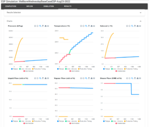
The production tubing is in mustard yellow, the tailpipe is blue, the casing gas return is in red and the liner annulus flow is in green. The wellhead return pressure is 3165 kPag and there’s some pressure change in the tailpipe which is caused by steam flashing. Not shown in the graphs are the tailpipe exit conditions; the gas volume fraction is 0.3 and the flow is mild slugging. This is what feeds the ESP gas separator. There’s nothing out of the ordinary in these results.
When we simulate the extended-reach well, things look a bit different. With the conventional well flowing 470 m3/d, we were targeting 846 m3/d with an 80% longer liner, assuming that the reservoir has the same inflow performance. No matter what we did, we couldn’t reach those rates. There was too much pressure drop in the liner and tailpipe, which caused high amounts of steam flashing. Even with 90% separation efficiency, there was too much gas in the ESP to lift to surface. The best we could reach was a 40% flow increase and operating conditions had to change significantly. We had to increase subcool to 10 C and allow a much lower FBHP of 2400 kPag. The conventional ESP had 15 stages and we increased that to 22 for this case to provide the same return pressure. The results are shown below:
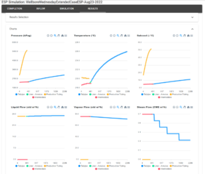
There’s a large pressure drop in the tailpipe, created by steam flashing. This effect feeds on itself in multiphase flow; the more flashing, the higher the velocity, which creates more friction, which decreases pressure, which increases flashing again. There’s a corresponding temperature change in the tailpipe as well. The tailpipe exit conditions have severe slugging at a gas fraction of 0.49. The ESP gas separator is handling almost 2.5x more gas flow than the conventional case which would have a significant impact on separation performance.
The conclusion we draw from this is that extended-reach SAGD wells require in-depth analysis to maximise their potential increase. In this particular case a 40% flow increase was achieved. It’s likely that a greater increase is achievable with a shorter liner; with less pressure drop along the liner and tailpipe, higher rates could probably be delivered. There are other options for increasing rates such as larger-diameter liners and tailpipes. These might not be economic or feasible, larger diameter liners are harder to land the longer they get.
In our future Wellbore Wednesdays we’ll look at finding a better length for this particular extended design, examine real inflow with distributed productivity index and also look at inflow control devices to further refine the inflow performance.
In the meantime, please reach out to Raj Bal, Stan Cena or Damien Hocking if you’d like to learn more, and follow us to keep up on the Wellbore Wednesday series. We’ll be discussing a variety of things in addition to SAGD wells as we go.