

Welcome again to Wellbore Wednesdays. After a brief hiatus we’re back on extended-reach SAGD producers, today looking at the hydraulics of ported tailpipes. If you want to get caught up on the previous articles, they’re here:
Simulating Performance of Extended-Reach SAGD wells – part 3
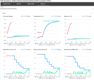
Back in part 2 of the series we looked at the performance of an extended-reach well with a tailpipe and a 1400 m lateral against a well with an 1800 m lateral and no tailpipe. 1400 m with a tailpipe was as far as we could push it, the liner lost 200 kPa along the liner annulus and the tailpipe lost another 675 kPa. Here’s what we saw in the simulation:
The large difference in liner pressure profile isn’t great for conformance, the toe would be pulling harder on the reservoir than the heel and the tailpipe produced a lot of gas traffic that has to be handled by the ESP’s gas separator. The 1800 m lateral with no tailpipe could deliver much higher rates with less dP than the shorter tailpipe completion.
We decided to revisit the 1400 m lateral and look at the performance of a ported tailpipe. This is a common design used by several operators. Ported tailpipes might have holes, perforations or vendor FCDs. The ports split flow in the liner annulus, instead of having the flow go in one direction from the heel to the toe, which increases pressure drop. It’s something like a gathering manifold. Each section of the liner carries some of the inflow a short distance, instead of the whole length of the liner. The ports in the tailpipe mean that only the section closest to the heel carries the highest rate, and the section closest to the toe carries the lowest rate. This reduces the frictional loss in the tailpipe.
The lateral starts at 502 m MD and ends at 1402 m. We chose to use 5 ports, 180 m apart starting at 502 m on the tailpipe. The last device is at 1402 m and then there’s almost 500 m to the open tail. The large distance is because the 101 mm tailpipe opening will flow a lot more than a port and so it will take a significant amount of flow from the liner towards the heel. We used a single 16 mm port at each location. This wasn’t a detailed, iterated design. The choice of 5 ports was more or less arbitrary, we’ve seen completions with one or more ports halfway along the tailpipe, completions with 2 or 3 groups of ports along the tailpipe and other variations.
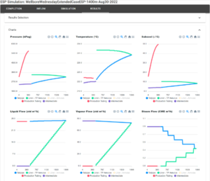
The rest of the completion and simulation was exactly the same as the original 1400 m case, rates, pump stages, FBHP, SOR, subcool etc. The simulation results are below.
We were solving to the same FBHP target of 2500 kPa with the same rates as before, so the liquid, vapour and steam flow rates are the same at the exit of the liner. The pressure profiles top-left are where the largest differences are. The tailpipe pressure profile is in blue. Instead of losing 675 kPa, we’re losing 250 kPa. That’s good, that’s less dP wasted on friction and more for inflow. The liner is in green. This is where the benefits of ports become clearer, instead of a 200 kPa differential along the liner, the largest difference is around 5 kPa and the pressure profile is basically flat. This is better for conformance. Also, the liner is running several hundred kPa lower overall than the example without ports, that dP is then available for production and not lost to friction. We didn’t try stretching this to 1800 m, the curve of the tailpipe pressure plot indicates that we’d have very high tailpipe dP at that length.
On the lower three graphs you can see the liquid flow profile. On the no-port graphs above, the tailpipe flow is carrying all the liquid and the liner rate is increasing from heel to toe with inflow. With ports, this flips around: the liner rates are lower, reasonably even and the tailpipe rate increases from toe to heel. On the graphs above, the small green peaks on the lower three graphs are the inlets of the ports and you can see the larger flow at the toe end that goes into the open tailpipe.
Next time we’ll look at this 1400 m liner again using packers with ports and we’ll start adjusting for varying inflow profiles. In the meantime, please reach out to Raj Bal, Stan Cena or Damien Hocking if you’d like to learn more, and follow us to keep up on the Wellbore Wednesdays series.